Smith charts were originally developed around 1940 by phillip smith as a useful tool for making the equations involved in transmission lines easier to manipulate. By using the smith chart, the impedance measurement can be made with the Web the smith chart was invented by phillip smith in 1939 in order to provide an easily usable graphical representation of the complex reflection coefficient γ and reading of the associated complex terminating impedance. Web 0.1 0.1 0.1 0.2 0.2 0.2 0.3 0.3 0.3 0.4 0.4 0.4 0.5 0.5 0.5 0.6 0.6 0.6 0.7 0.7 0.7 0.8 0.8 0.8 0.9 0.9 0.9 1.0 1.0 1.0 1.2 1.2 1.2 1.4 1.4 1.4 1.6 1.6 1.6 1.8 1.8 1. Those with negative real parts map outside the circle.
Complex numbers with positive real parts map inside the circle. Web the smith chart presents a large amount of information in a confined space and interpretation, such as applying appropriate signs, is required to extract values. Web what is a smith chart? Web the smith chart is a powerful graphical tool that is extensively used by rf engineers to rapidly determine how a given impedance can be transformed into another one. Smith charts were originally developed around 1940 by phillip smith as a useful tool for making the equations involved in transmission lines easier to manipulate.
Complex numbers with positive real parts map inside the circle. A network analyzer ( hp 8720a) showing a smith chart. Web the smith chart is a powerful graphical tool that is extensively used by rf engineers to rapidly determine how a given impedance can be transformed into another one. Web the smith chart is used to display an actual (physical) antenna's impedance when measured on a vector network analyzer (vna). Γis defined as the ratio of electrical field strength of the reflected versus forward travelling wave.
Smith Chart Graph Paper to download and print Electronic Products

Smith Chart PDF Printable
Smith Chart Template Edit, Fill, Sign Online Handypdf
The Smith Chart A Vital Graphical Tool DigiKey

Smith Charts
2024 Smith Chart Fillable, Printable PDF & Forms Handypdf
Smith Charts
Printable Smith Chart

2024 Smith Chart Fillable, Printable PDF & Forms Handypdf
Printable Smith Chart Printable Templates
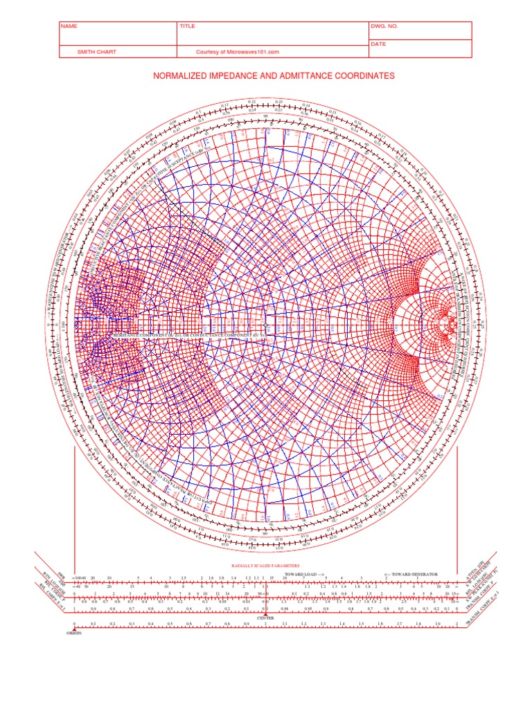
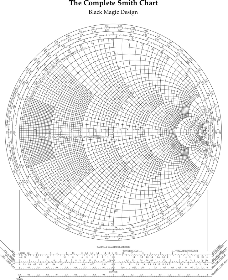
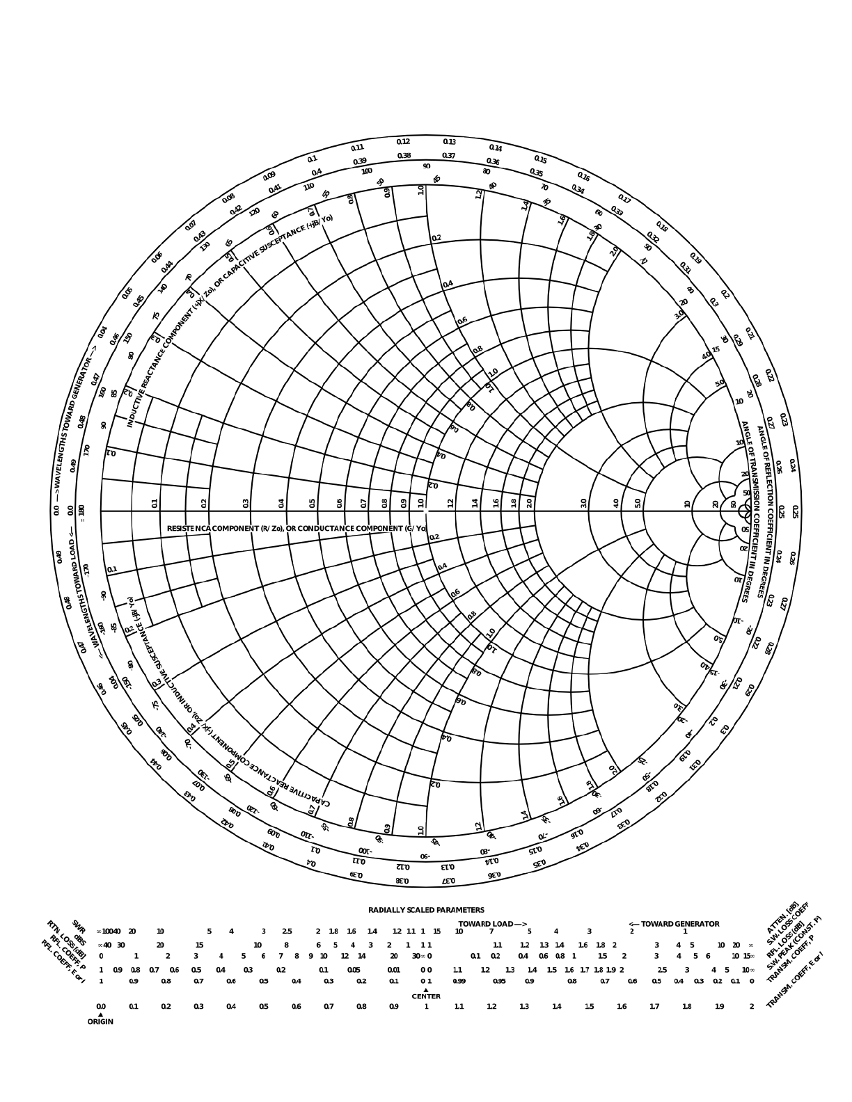
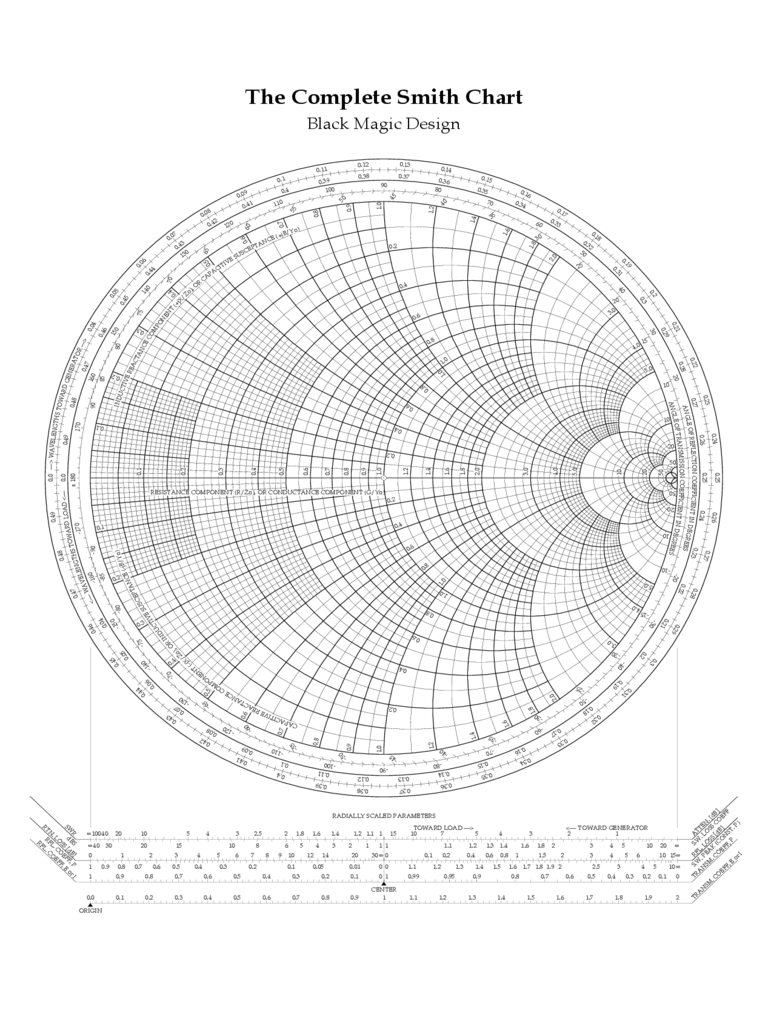
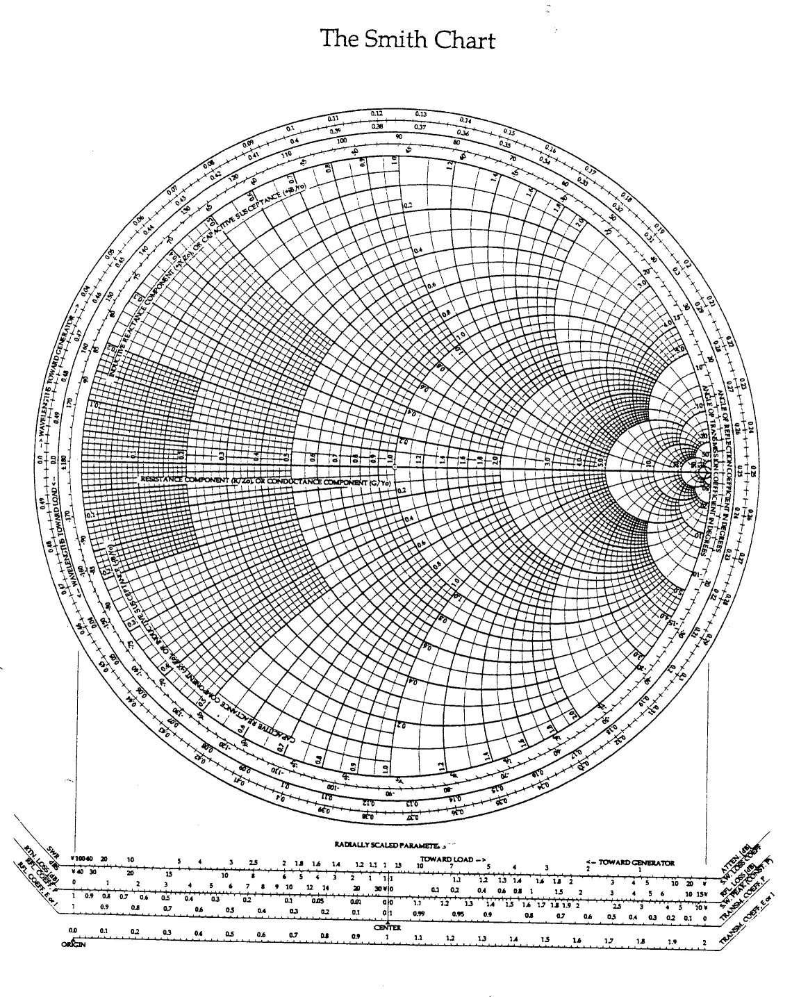
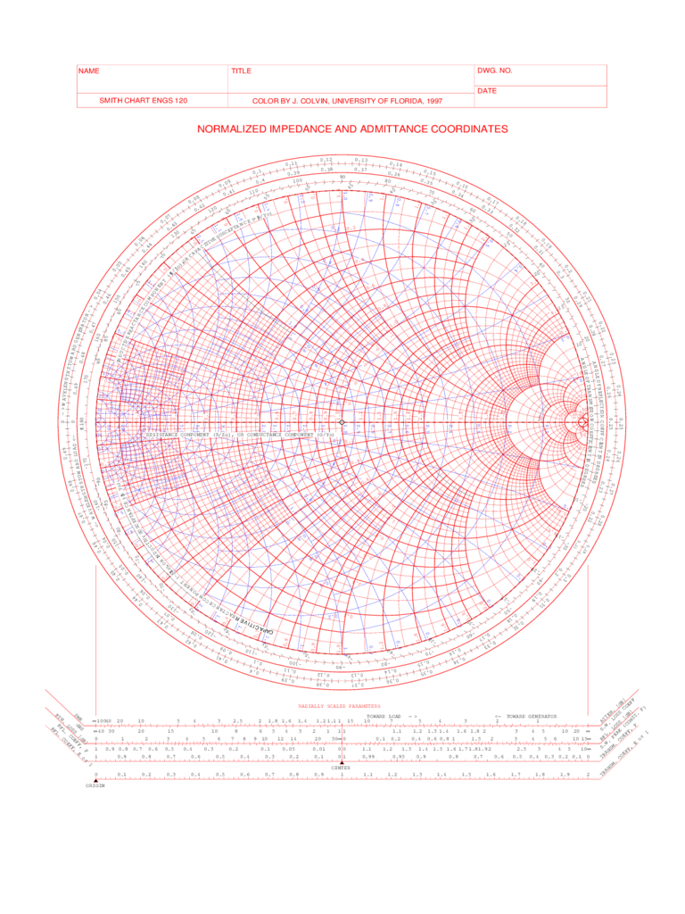
A smith chart is utilized by examining the load and where the impedance must be matched. Γis defined as the ratio of electrical field strength of the reflected versus forward travelling wave. Web the smith chart is a polar plot of the complex reflection coefficient, γ, for a normalized complex load impedance zn = r + jx, where r is the resistance and x the reactance. Web the smith chart was invented by phillip smith in 1939 in order to provide an easily usable graphical representation of the complex reflection coefficient γ and reading of the associated complex terminating impedance. Smith charts were originally developed around 1940 by phillip smith as a useful tool for making the equations involved in transmission lines easier to manipulate. Web the smith chart presents a large amount of information in a confined space and interpretation, such as applying appropriate signs, is required to extract values. Web 0.1 0.1 0.1 0.2 0.2 0.2 0.3 0.3 0.3 0.4 0.4 0.4 0.5 0.5 0.5 0.6 0.6 0.6 0.7 0.7 0.7 0.8 0.8 0.8 0.9 0.9 0.9 1.0 1.0 1.0 1.2 1.2 1.2 1.4 1.4 1.4 1.6 1.6 1.6 1.8 1.8 1. Web the smith chart is a powerful graphical tool that is extensively used by rf engineers to rapidly determine how a given impedance can be transformed into another one. By using the smith chart, the impedance measurement can be made with the Web what is a smith chart? Web radio frequency engineering tools. Transmission coefficient, which equals unity plus reflection coefficient, may also be plotted (see below). Those with negative real parts map outside the circle. A network analyzer ( hp 8720a) showing a smith chart. Complex numbers with positive real parts map inside the circle.
A Smith Chart Is Utilized By Examining The Load And Where The Impedance Must Be Matched.
Web the smith chart is a powerful graphical tool that is extensively used by rf engineers to rapidly determine how a given impedance can be transformed into another one. Web the smith chart is a sophisticated graphic tool for solving transmission line problems. Web what is a smith chart? Web radio frequency engineering tools.
Complex Numbers With Positive Real Parts Map Inside The Circle.
By using the smith chart, the impedance measurement can be made with the Smith charts were originally developed around 1940 by phillip smith as a useful tool for making the equations involved in transmission lines easier to manipulate. Web the smith chart is used to display an actual (physical) antenna's impedance when measured on a vector network analyzer (vna). Web the smith chart presents a large amount of information in a confined space and interpretation, such as applying appropriate signs, is required to extract values.
Transmission Coefficient, Which Equals Unity Plus Reflection Coefficient, May Also Be Plotted (See Below).
Web the smith chart is a polar plot of the complex reflection coefficient, γ, for a normalized complex load impedance zn = r + jx, where r is the resistance and x the reactance. Those with negative real parts map outside the circle. Web the smith chart was invented by phillip smith in 1939 in order to provide an easily usable graphical representation of the complex reflection coefficient γ and reading of the associated complex terminating impedance. A network analyzer ( hp 8720a) showing a smith chart.
Web 0.1 0.1 0.1 0.2 0.2 0.2 0.3 0.3 0.3 0.4 0.4 0.4 0.5 0.5 0.5 0.6 0.6 0.6 0.7 0.7 0.7 0.8 0.8 0.8 0.9 0.9 0.9 1.0 1.0 1.0 1.2 1.2 1.2 1.4 1.4 1.4 1.6 1.6 1.6 1.8 1.8 1.
Γis defined as the ratio of electrical field strength of the reflected versus forward travelling wave.